


2.50 Inch Exhaust Fabrication Kit
2.50" Exhaust Fabrication Kit
Professional Modular Mock-Up System (STL Files)
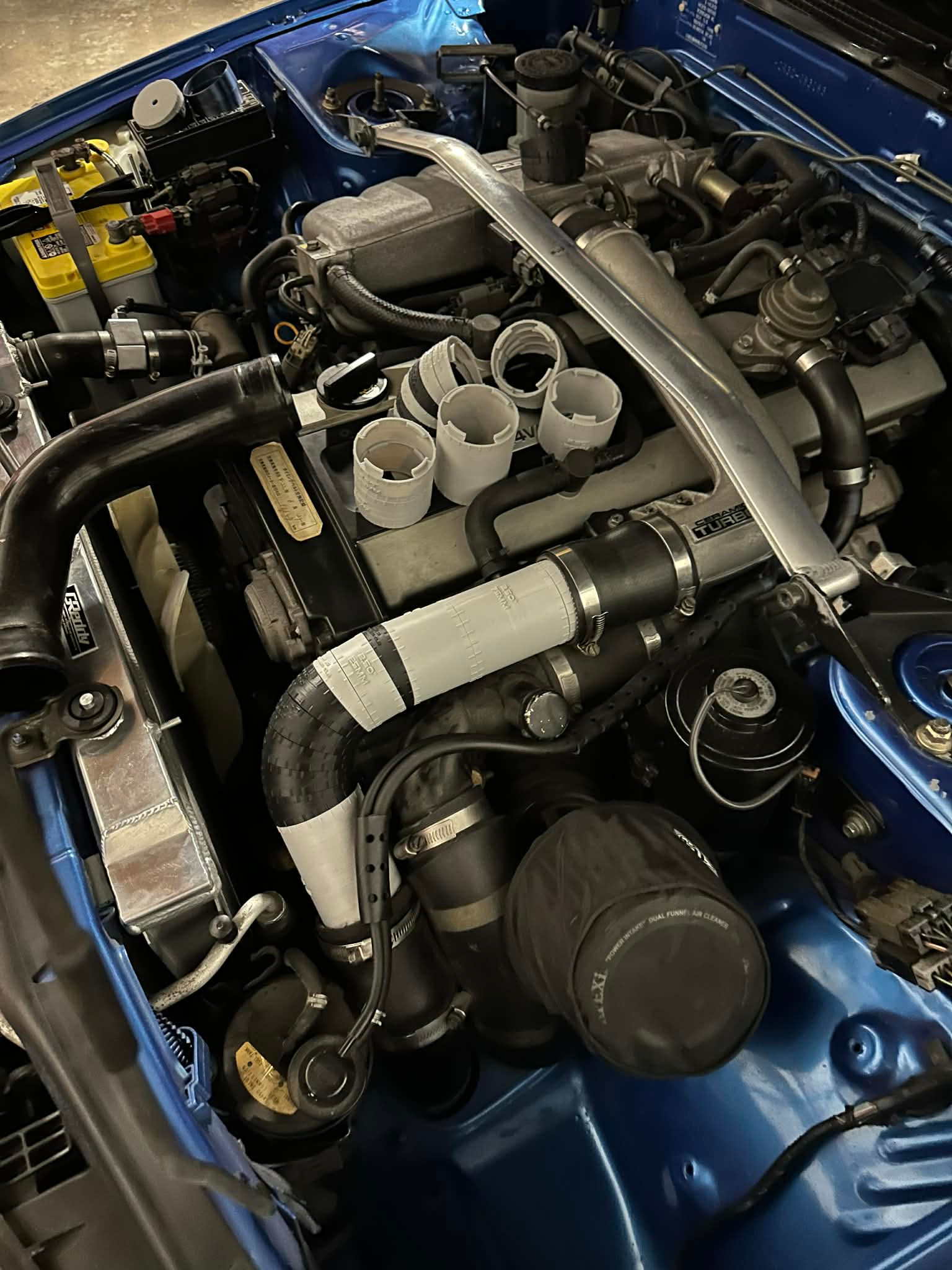
Designing a custom exhaust system can be time-consuming, expensive, and often involves trial and error with costly materials. This 2.50" Exhaust Fabrication Kit eliminates that guesswork by giving you a precise, modular way to plan your entire system before you ever cut or weld metal.
Built for fabricators, performance builders, and serious enthusiasts, this kit allows you to physically mock up full exhaust runs using 3D printed components, accurately test fitment, and fine-tune routing in a controlled, repeatable way.
Every part in the system has been developed with real-world fabrication in mind — from true-to-scale dimensions and centre line radius options, to clearly marked angle increments that let you measure and replicate your design with confidence.
Whether you're building a high-performance system, developing a custom downpipe, or refining complex routing, this kit helps you:
- Visualise your build before fabrication
- Reduce wasted material and costly mistakes
- Accurately transfer designs into metal
- Improve speed and workflow efficiency
📏 System Dimensions & Specifications
This kit is engineered around a true 2.50" (63.50mm) exhaust system, ensuring accurate scaling for real-world fabrication.
🔩 Core Dimensions
- Pipe Diameter: 2.50" (63.5mm)
- Expander Fitment Range: 59.3mm - 64.5mm internal diameter
- Straight Sections: 20mm to 110mm lengths
- Angle Markings: 15° increments on all bends
🔄 Bend Geometry Options
Several centre line radius (CLR) options are included to suit different build requirements:
- 63.5mm (2.50") CLR – tight radius for compact routing
76.2mm (3.00") CLR – compact radius for tighter bends
79.375mm (3.125") CLR – compact-balanced radius for versatile routing
82.5mm (3.25") CLR – balanced radius for general use
95.25mm (3.75") CLR – wider radius for smoother flow
📐 Available Bend Angles
9° · 15° · 18° · 22.5° · 27° · 30° · 36° · 45° · 54° · 60° · 63° · 67.5° · 72° · 75° · 81° · 90°
All bends include start, middle and end connection pieces for seamless modular assembly.
🧭 Precision Marking System
- Bends marked in 15° increments for accurate angle tracking
- Centreline tools allow:
- 90° marking (3 reference points)
- 180° marking (2 reference points)
This ensures your mock-up can be directly and accurately transferred into metal fabrication.
Any material can be used but materials with a higher durability will be better due to the entire kit being 3D printed along with the clips that attach the pieces together.
No supports on most of the parts, however the large bend angles will need supports
Some models will need to be re-orientated before being able to print.
Increase wall count so no infill is printed in the mock up tubes, the other pieces can be printed with 4 walls and minimum 25% infill.